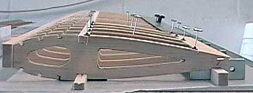
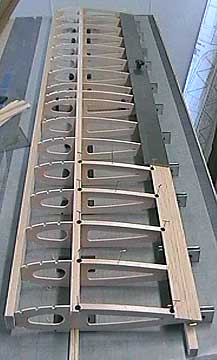
Rib

boyboy

عضو جدید
(aircraft)


Rib 
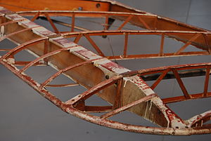
Wing ribs of a de Havilland DH.60 Moth
In an aircraft, ribs are forming elements of the structure of a wing, especially in traditional construction.
By analogy with the anatomical definition of "rib", the ribs attach to the main spar, and by being repeated at frequent intervals, form a skeletal shape for the wing. Usually ribs incorporate the airfoil shape of the wing, and the skin adopts this shape when stretched over the ribs.​
Type of ribs

There are several types of ribs. Form-ribs, plate-type ribs, truss ribs, closed-ribs, forged ribs and milled ribs, where form-ribs are used for light to medium loading and milled ribs are as strong as it can get.
Form-ribs are made from a sheet of metal bent into shape, such as a U-profile. This profile is place on the skin, just like a stringer, but then in the other direction.
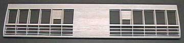
Plate-type ribs consist of sheet-metal, which has upturned edges and (often has) weight-saving holes cut into it.
Truss ribs are built up out of profiles that are joined together. These joints require great attention during design and manufacture. The ribs may be light or heavy in design which make them suitable for a wide range of loads.
Closed-ribs are constructed from profiles and sheet metal and are suitable for closing off sections of the wing (e.g.: the fuel tank). Here too, particular care must be taken with the joints and this type of rib is also suitable for application in a variety of loading conditions.
Forged ribs are manufactured using heavy press-machinery. The result is fairly rough; for more refined parts, high-pressure presses are required, which are very expensive. Forged pieces (usually) have to undergo further treatment (for smoother edges and holes). Forged ribs are used for sections where very high loads apply - near the undercarriage for example.
Milled ribs are solid structures. They are manufactured by milling away excess material from a solid block of metal (usually using computer-controlled milling machines). The shape of these ribs is always accurately defined. Such ribs are used under similar conditions as those for forged ribs.
Ribs are made out of wood, metal, plastic, composites, foam. The wings of kites[1], hang gliders [2], paragliders [3], powered kites [4], powered hang gliders, ultralights, windmills [5] are aircraft that have versions that use ribs to form the wing shape.
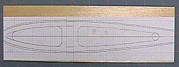
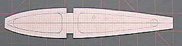
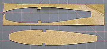
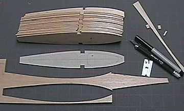
For full size and flying model aircraft wing structures that are usually made of wood, ribs can either be in one piece (forming the airfoil at that rib's "station" in the wing), or be in a three-piece format, with the rib web being the part that the one-piece rib consisted of, with capstrips for the upper and lower edging of the rib, running from the leading edge to the trailing edge, being the other two component parts.​
 

boyboy

عضو جدید
Aeronautics: Aerodynamic Wing Rib Design
In this section I'm showing the basics of how to design and draw an airplane wing rib. I developed and tested this particular wing rib for a rocket-launched glider. It needed to be balanced for both "high speed - low drag", and "low speed - high lift". That's really an oxymoron in term and application, so a reasonable compromise must be found. I tested this design on a small model that launched to about 350 feet in 1.5 second. This wing rib was the first thing that I designed at the very beginning of the project, and it held true throughout. It took another year and a half of trial and error to develop the glider, rocket body, and glider release/parachute mechanism. It was launched, and flown without error or damage 72 times.


The first aspect of the wing rib to decide upon; is the percent of the Cord Height (thickest part - line C) of the wing rib, to the length; from Leading edge to Trailing edge. Note that line "A" is 36% of line "B". 36% is a very median amount. Many higher speed, but subsonic aircraft measure 40 or even 42 percent, while a performance glider might measure closer to 25 percent.

The next aspect is, Cord Height to Rib Length Ratio. In this ratio, you must consider, not only the effect on drag and lift, but strength of the rib and wing, also. The ratio here, is 8:1.
This is a suitable way of forming the curves in the leading edge. You'll notice the I adjusted the size of the oval to create a curve between the leading edge and highest point of the cord. There are a variety of ways to do this, but shown, is about the quickest and easiest. Notice the small size of the oval used for the leading edge. This is not typical for a low or moderate speed. I specially decided on a sharper leading edge for the speed attained during the "rocket" launch.
Now you can see, I've flipped the oval in order to draw the back side of the curve.
The center line of the oval used for the curve, at the bottom of the leading edge must NOT extend to the cord, but to the base line.
Now you've got the basic shape, and it's reading for modifying for the leading and trailing edges, spars and stingers. I found that "boxing" the top (only) of the leading edge added extreme strength without much weight.
You'll notice (below) that even though apparently setting flat, that the angle of attack is about 4.5 degrees.
I built this image very fast and it's a bit rough, but with some time and care they can be completed with fine detail and smoothness. It's just a matter of how much time you put into the accuracy.

I've been meaning to work on this image to show it can be done with more quality. This better, but I still didn't really spend much time on it. The bigger you make it, even if then you need to shrink it for your model, the better the quality of detail you can arrive at. - Ed

Most any drawing software that has reasonably accurate (0.01) scaling and grid options may be used for this application.
 

boyboy

عضو جدید
How to Make a Set of Ribs for a Constant Chord Wing

The simplest type of wing to build from scratch is one having a constant chord planform.
A rib template can be made from a hard material such as thin plywood or Formica. A hobby knife is used to cut around the pattern to make as many ribs as needed.
Alternatively, rib blanks can also be stacked and cut using a power tool such as a scroll or band saw. The latter methods are usually the fastest, but not always the best.
The rib blanks for the stack are usually rectangular which means a lot of wood goes to waste. Additionally the stack of blanks is tall and narrow and spongy which means it can flex or distort. I have run into this problem more often than not. The end result is a lot of wasted wood and an unusable set of ribs. My preferred method is to cut the ribs around the pattern. It takes more time, but has given me a better result.
I will use a scroll saw to cut short stacks of ribs. I usually stack the ribs for the wing center section to trim off some of the rib to account for the sheeting after cutting and sanding the rib blanks. I don't stack ribs more than 1/2" high to cut with the saw for the reason mentioned above.
Modify individual ribs or matched pairs as necessary to include cut-outs for landing gear blocks, holes for servo leads and pushrods, etc.
The first step is to plot an airfoil from which the rib pattern is created. Add details to the drawing such as the leading edge, trailing edge, spars and sheeting. It is helpful to draw in other details such as the holes for servo leads even if they will not be in every rib.
It is generally wise to place the main spars at the thickest section of the airfoil. The farther the spars are spaced apart, the stronger the wing will be.
Also see

The set of ribs presented here were used to build the wing for Rustik. I had only a rough idea what the wingspan would be at the time I cut these ribs. I cut some extra rib blanks to give myself flexibility.
I do not go along with the current design philosophy made popular by 3D aircraft of spacing ribs 7" apart. I like ribs spaced no more than 2-1/2" apart and even closer when the wing will be fully sheeted.
This wing will be fully sheeted, have no dihedral and be constructed in one piece. The spars and sheeting will be full span and shear webs will be used. No dihedral bracing will be necessary as the wing will be adequately strong without it. Four servos will be used in the wing (2 ea. flaps and ailerons). The control surfaces will be built up separately.
These ribs have large internal cut-outs to save weight and allow passage of servo leads. The cut-outs are optional if you build a wing using torque-rod driven ailerons.
Always drill a hole in every rib to allow the wing to vent. The more ribs there are the more venting there should be. You may need to drill additional holes if you can't make the hole larger.
Drill a hole in both the forward and aft portions of the rib if the wing has shear webs. Venting is important to prevent your wing from exploding from sudden changes in atmospheric pressure while flying. I have never seen it happen but I have heard of it happening particularly among sailplanes that fly at higher altitudes.

1/16" aircraft plywood is used for the master pattern. Any thin, hard material will work as long as you can shape it. Draw a centerline on the hard pattern using an ink pen. Attach the paper pattern to the plywood using spray glue being sure to align the centerlines.
The pattern is cut slightly over-size and then carefully sanded to shape. The pattern should be as stable as possible. Interior cut-outs will be made after the ribs are cut. Note that the spars are located at the thickest point of the wing.
Sandpaper is spray glued to the back of the pattern to prevent it from slipping when cutting the ribs.
The ribs are cut from several sheets of lightweight contest balsa. I used a hobby knife to cut around the plywood pattern. The spar cut-outs are deliberately undersize so that they can be sanded to a perfect fit.
The ribs are more flexible and fragile with the internal cut-outs so I will make those after the ribs are sanded to shape.
Square the stack of ribs and pin or nail them together so they can be gang-sanded. T-Pins are not long enough in this case so I used small nails from both sides of the stack. The nails are located within the cut-outs that will be made later. Be sure to use enough pins or nails so the stack can not shift while sanding.
 

boyboy

عضو جدید
The ribs have been sanded to a uniform shape using a small sanding block (not shown). The small hardwood sanding block shown here was used to finish the spar cut-outs. Scrap pieces of spar material are used to check the progress during sanding. It should be obvious that the spar notches in the ribs should be sanded to match the spars. Don't sand the scrap spars to match the spar notches.
Take careful measurements to ensure the stack of ribs is as uniform as possible. A diagonal line drawn across the ribs indicates the order in which the ribs are stacked as well as which side is up.
Do not remove the pins until you are absolutely satisfied with the rib set.
Optional Make the internal cut-outs. This operation does not need to be as precise as the outline so the ribs are divided into two stacks. A scroll saw speeds things up. Make the cut-out in the plywood pattern. The outline of the cut-out is traced on the topmost rib. Holes are drilled to allow passage of the scroll saw blade.
If you do not own a scroll saw you can use the plywood pattern and a hobby knife to make the cut-outs. Normally I drill the corners with the ribs stacked and then use a knife and straight-edge to connect the corners of each rib individually.
The completed rib set. The three ribs at the bottom are cut from thicker stock. The center of these three ribs is 1/4" balsa and will be in the center of the wing. The ribs on either side of the center rib are 3/16" balsa and will be positioned directly over the wing saddles. These two ribs must fully support the wing so the cut-out is smaller to ensure the ribs will have adequate strength.
On the right is the plywood pattern.
In some cases additional holes or cut-outs will be needed. For example, the center ribs may need to be cut in half to allow the use of dihedral braces. Select the appropriate ribs from their position in the stack taking right and left wing panels into account. Make any modifications necessary. When the ribs are completed put them in a safe place until you need them.
Always save your templates.

Lightening Wing Ribs

I received an e-mail from a person who wanted more information about the strength of a rib that had large internal sections removed. It is a legitimate concern simply because nobody wants to build a model that self-destructs in flight.
I have used ribs similar to this in several of my models and have had no problems. To date not a single rib has broken in flight or from handling. However, you do have to be careful when handling the wing. For example the ribs used for Great Gonzo have a 1/4" outline. The wing must be lifted by grasping the spars or the center section sheeting. There is a good possibility that the rib would break if the wing were lifted by supporting it under a rib.
I have had to repair Great Gonzo three times due to damage that occurred on the ground on exceptionally windy days. The first damage was caused when Great Gonzo blew off a table at the field and fell several feet to the ground. It flipped over in the air and landed upside-down directly on the wing which flexed and tossed the model back into the air. Damage incurred was a broken leading edge near the wing root.
The other two times both occurred during take-off. Great Gonzo was blown over when it turned cross-wind (pilot error) and cart-wheeled several times. The first time this happened a main spar was broken as well as the leading edge. The second time the tail end of the fuselage had a minor crack and the leading edge of the wing broke again. Notably, no wing ribs were broken in any of these incidents.
My Stik 30 has smaller cut-outs because the model was designed for higher performance. As I mentioned on the My Stik 30 page, the ailerons can deflect up to 45° in each direction on high rates. The roll rate is so fast I can not count them. Additionally, when the Webra .32 was mounted on it I put the model in several full-throttle, terminal-velocity dives of several hundred feet. The airframe had no problems with this.
My Stik 30 uses the same wing that was on the first version that I crashed on take-off at full throttle. That crash was due to putting a wing tip in the ground and cart-wheeling the plane (my favorite way to break airplanes apparently) across the field.
The wing was subjected to a significant torsion load but the only damage to it were a couple dents in the wing tips and a broken turbulator spar. None of the ribs were damaged. The fuselage was totaled.
As far as weight savings goes, it is all relative. If you are trying to shave every ounce of weight from your aircraft, then the effort to remove weight from the ribs is worth it. On the other hand, the weight savings of the ribs alone probably is only an ounce or so for a .40 size ship assuming the use of contest balsa. If the ribs are made from heavier wood then the weight-savings will be greater.
The following images show the wing construction of My Stik 30. Again, this wing survived a full throttle cartwheel across the field and is still in use.
My Stik 30's wing has turbulators on the top and bottom of the forward portion of the wing and cap strips on the aft portion of the wing.

Note the shallow grooves in the spars (a little deeper than 1/64"). These make it very easy to align the shear webs between the spars and provide additional gluing area. The grooves can be cut on a table saw or router table. The black items you see on the T-pins are called Pin Clamps and are manufactured by Rocket City.

Another view of the wing under construction. The wing is light and strong. There are twelve one-piece, full-span wood strips in the construction:
  • 3/8" x 3/4" Leading edge (1)
  • 1/8" square Turbulators (6)
  • 1/4" x 3/8" Main Spars (2)
  • 1/16" x 1-1/2" Trailing edge sheet (2)
  • 3/8" square Trailing edge (1)
The completed wing.
 

boyboy

عضو جدید
How-To Articles for Model Aircraft Builders

These are techniques that I have used successfully to achieve the desired result. They certainly aren't the only way and possibly not even the best way. I only claim that these methods are proven to work.


Many of these articles were prompted by questions from visitors to this website. If there is something on the site that you would like more information about or there is something you would like to see then please do not hesitate to contact me.
Construction Techniques

  • Install Robart Hinge Points — A 5-part article demonstrating several methods of installing Hinge Points. Article also contains information appropriate to the installation of any type hinge.
  • Make Film Hinges — Also called Monokote Hinges.
  • Mount a Pilot Bust — A solid mounting that won't let loose without a force that destroys the plane.
Finishing

Testing compatibility of finishes


If you apply painted finishes then do yourself a favor and make a sturdy frame to test finishing techniques.
The last two photos are testing the compatibility of clear epoxy paint applied over vinyl decals. I found they were not compatible but could work if very light sprayed coats were built up.
Most coverings can be peeled off easily when testing is complete. Sand the frame and it's ready for next time.


boyboy

عضو جدید
Tools You Can Make

Miscellaneous


بالا